Ever wondered how a welder turns a drawing into a strong weld? Welding symbols are the key, telling welders exactly what to do to get the job done right.
These weld symbols are crucial for making sure every weld meets safety and design standards. Knowing how to read and use these symbols is a must-have skill for welders to avoid mistakes and produce top-notch work.
Understanding them is essential if you want to read welding blueprints, pass certification tests, and work on professional projects.
This guide will walk you through the basics of welding symbols, what they mean, and how you can easily read and understand them.
Quick Takeaways:
- Welding symbols are like a universal language for welders.
- They tell you the type of weld, its size, and exact location.
- Key parts include: arrow line, reference line, and symbol.
- Common weld symbols: fillet, groove, plug, spot, and seam.
- Learning them improves accuracy, safety, and efficiency.
Understanding Symbols in Welding
Welding symbols contain specific information about weld types, sizes, and locations through standardized pictures and markings. These symbols differ from weld symbols in their complete structure, and they serve as the primary communication tool between engineers and welders.
Definition of Welding Symbols
Welding symbols guide welders in preparing, welding, and finishing weld joints. They are standardized drawings that show you exactly how to complete a weld.
A welding symbol is a complete picture with multiple parts. It contains all the information you need to know about a specific weld joint.
The American Welding Society (AWS) publishes and maintains national standards for welding symbols in the USA. The official standard is called "ANSI/AWS A2.4 Standard Symbols for Welding, Brazing, and Nondestructive Examination."
The International Organization for Standardization (ISO) also maintains standards in ISO 2553. Both standards have small differences, but they work the same way.
Purpose and Importance
Welding symbols ensure you understand what engineers and designers require for each weld. They provide the best way to access all the information you need to do your job effectively.
Understanding welding symbols is critical for anyone working in a fabrication shop. Without them, you cannot follow welding codes properly.
These symbols tell you important details like:
- Weld type and location
- Size requirements
- Length and spacing
- Preparation needed
- Finishing requirements
The symbols prevent mistakes and ensure all welders perform the same job in the same way. They save time by putting complex instructions into simple pictures.
Weld Symbol vs Welding Symbol
It's important to note that the terms "weld symbol" and "welding symbol" are not interchangeable. Many people use these terms incorrectly.
A weld symbol is just one small part. It shows the type of weld you need to make. Examples include fillet, groove, or plug weld symbols.
A welding symbol is the complete picture. It includes the arrow, reference line, tail, and the weld symbol placed on it.
You place weld symbols on the reference line of welding symbols. The welding symbol provides full instructions, whereas the weld symbol indicates the weld type.
Think of it this way: the weld symbol is like one word, but the welding symbol is the complete sentence with all the details you need.
Also Read: The Ultimate Weld Symbol Chart Cheat Sheet
Basic Elements of a Welding Symbol
Every welding symbol has four main parts that work together to give you complete welding instructions.
The reference line holds the weld information, the arrow points to where you weld, and the tail contains special notes about the welding process.
1. Reference Line
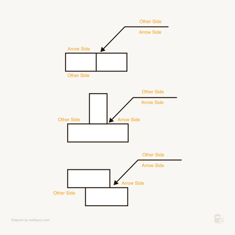
Image credit: https://weldguru.com/welding-symbols/
The reference line is the main part of any welding symbol. It looks like a straight horizontal line that runs across the symbol.
This line holds most of the information you need as a welder. You will see weld symbols, sizes, lengths, and other details placed on or near this line.
The reference line has two sides that mean different things. The bottom side connects to the arrow side of your weld joint. The top side represents the other side of the joint.
When you see a weld symbol below the reference line, you weld on the arrow side. When the symbol sits above the line, you weld on the other side. This placement tells you exactly where to put your welds.
The reference line acts as an anchor to which all welding symbols are tied. Without this line, the other parts of the welding symbol would not make sense.
2. Arrow and Arrow Side
Image credit: https://weldguru.com/welding-symbols/
The arrow connects to the reference line and points directly at your weld joint. This arrow shows you exactly where to apply the weld on your workpiece.
The arrow can point up, down, left, or right, depending on the drawing. No matter which direction it points, it always identifies the arrow side of your joint.
For most welds, the arrow just shows the location. But for groove welds, the arrow has a special job. It points to the piece of metal that needs the bevel cut or preparation work.
You might see the arrow with a break or bend in it sometimes. This break indicates that the arrow points to a specific member or plate requiring special attention during welding.
The arrow designates which side is the arrow side of the weld joint. This designation helps you understand exactly where to position yourself and your welding equipment.
3. Other Side
The other side refers to the opposite side of your weld joint from where the arrow points. This side always relates to the top of the reference line.
When you see weld symbols above the reference line, you need to weld on the other side. This means you will weld on the back or far side of the joint from the arrow.
The other side concept helps prevent confusion on complex drawings. You always know which side needs welding based on where the symbols appear on the reference line.
Some welding symbols show information on both sides of the reference line. This means you need to weld both the arrow side and the other side of the same joint.
Understanding other side placement becomes critical when reading blueprints with multiple weld joints. Each arrow and reference line combination tells you exactly where each weld goes.
4. Tail and Its Function
The tail appears at the end of the reference line as a small triangular shape. You will find important welding process information and special instructions written inside this tail.
Common information in the tail includes welding process codes like GMAW, GTAW, or SMAW. You might also see welding procedure numbers or specific filler metal requirements.
The tail can contain finishing instructions, inspection requirements, or safety notes. This extra information helps you complete the weld job according to engineering specifications.
If the welding symbol does not need extra information, the tail can be removed completely. Many simple welding symbols do not include a tail section.
The tail contains specific instructions and references for the welding process that you cannot show with basic symbols alone. This makes the tail essential for complex welding operations.
Types of Welds and Their Symbols

Image credit: https://weldguru.com/welding-symbols/
Each weld type has its own unique symbol that tells welders exactly what kind of joint to create. The most common welding symbols include fillet welds for corner joints, groove welds for edge-to-edge connections, plug and slot welds for overlapping pieces, and spot welds for single-point connections.
1. Fillet Weld Symbol
The fillet weld symbol looks like a right triangle. It's the most used weld symbol you'll see on drawings.
Fillet welds create strong joints between two pieces of metal that meet at an angle. You'll use them for T-joints, lap joints, and corner joints.
The symbol shows up as a triangle on the reference line. When you see numbers next to it, they tell you the leg size of the weld.
Key features of fillet weld symbols:
- Triangle shape pointing toward the joint
- Leg size shown as numbers (like 1/4 or 6mm)
- Length may be specified on the right side
- Can appear above or below the reference line
The fillet weld symbol tells you to deposit weld metal in the corner formed by two pieces. Your finished weld should have a triangular cross-section.
2. Groove Weld Symbol
Groove weld symbols show different ways to prepare metal edges before welding. These are the second most common welds you'll encounter.
Square groove welds use the simplest symbol - just a straight line. You don't bevel the edges at all. The pieces either fit tightly together or have a small gap called root opening.
V-groove welds show a V-shaped symbol. Both pieces get beveled to form a V-shaped opening. You'll see angle measurements and root opening dimensions.
Bevel groove welds combine a straight line with an angled line. Only one piece gets beveled while the other stays square.
Common groove weld types:
- Square groove - straight line symbol
- V-groove - V-shaped symbol
- Bevel groove - straight line plus angle
- U-groove - curved bottom symbol
- J-groove - curved on one side only
The groove weld symbol placement tells you which side needs preparation. A broken arrow line points to the specific piece that gets beveled. (Also Read: Bevel Weld Symbols and Types in Welding)
3. Plug and Slot Weld Symbols
Plug and slot welds join overlapping pieces through holes. The symbols look like rectangles with specific markings inside.
Plug welds fill round holes with weld metal. You drill or punch holes in the top piece, then weld through to the bottom piece.
Slot welds work the same way but use elongated holes instead of round ones. Both create strong mechanical connections.
Symbol details include:
- Rectangle shape for basic symbol
- Hole diameter or slot dimensions
- Number of welds needed
- Spacing between multiple welds.
You'll find these plug and slot weld symbols on drawings where bolting isn't practical. They're common in structural work and sheet metal fabrication.
The filled rectangle tells you to make the weld flush with the surface. An unfilled rectangle means the weld can be slightly raised.
4. Spot and Seam Weld Symbols
Spot welds create single-point connections between overlapping sheets. The symbol shows as a circle on the reference line.
Spot weld symbols include important details like weld diameter and spacing. You'll see numbers that tell you the size of each spot and how far apart to place them.
Seam welds are like continuous spot welds. They use high heat to create long, linear joints. The symbol looks similar to spot welds but includes length information.
Essential spot and seam weld details:
- Circle symbol for spot welds
- Diameter measurements in the circle
- Pitch (center-to-center spacing) on the right
- Number of spots when specified
These welds are common in automotive work and sheet metal assembly. The seam weld symbol might include shading to show whether it's a continuous or intermittent seam.
Both symbols can appear above or below the reference line to show which side gets welded.
Supplementary and Additional Welding Symbols
Supplementary welding symbols add extra details to basic weld symbols and help specify important requirements like location, finish, and contour. Field weld and all-around symbols are two of the most common types you will encounter on welding drawings.
Supplementary Symbols
Supplementary symbols enhance basic weld symbols by providing additional specifications and instructions. These symbols work together with standard weld symbols to give you complete information about how to make the weld.
The AWS A2.4 standard defines 9 main supplementary symbols:
- Weld all around
- Field weld
- Melt-through
- Consumable insert (square)
- Consumable insert (rectangle)
- Spacer (rectangular)
- Flush or flat weld contour
- Convex weld contour
- Concave weld contour
You will find these symbols placed in specific locations around the basic welding symbol. They inform you about the weld's finish, the work location, and any special requirements.
Supplementary symbols clarify finish, contour, and specific characteristics that are crucial for meeting design specs. Without these symbols, you might miss important details about how the final weld should look and perform.
Field Weld Symbol
The field weld symbol looks like a small flag or pennant. You will see it placed at the intersection of the reference line and arrow on welding symbols.
This symbol tells you to complete the weld at the job site, not in the shop. Field welds happen during construction or assembly when parts cannot be welded in a controlled workshop environment.
Field welds often require special considerations:
- Portable welding equipment
- Weather protection
- Limited positioning options
- Different quality control procedures
You need to plan for these challenges when you see the field weld symbol. The working conditions will be different from shop welding, so you may need to adjust your technique or equipment.
All-Around Symbol
The all-around symbol appears as a small circle placed at the intersection of the reference line and arrow. This symbol means you must weld completely around the entire joint perimeter.
When you see this symbol, you need to make a continuous weld that goes all the way around the part. There should be no gaps or breaks in the weld.
Common applications include:
- Pipe connections
- Structural tube joints
- Pressure vessel attachments
- Tank nozzles
The all-around symbol often appears with other symbols to give you complete welding instructions. You might see it combined with field weld symbols when the circular weld must happen at the job site.
Pay attention to access and positioning when making all-around welds. You may need to rotate the part or use special techniques to reach all areas of the joint.
Best Practices for Reading Welding Symbols
Reading welding symbols correctly starts with following a clear process. You should always begin at the arrow and reference line to understand where the weld goes.
Start with the basics:
- Look at the arrow first - it points to the joint location
- Find the reference line - this is your starting point
- Check if symbols are above or below the line
Next, you need to identify the specific weld symbol type. The welding symbols guide welders in understanding fillet welds (triangles), groove welds (V-shapes), and other common types.
Key identification steps:
- Recognize fillet welds as triangles
- Spot groove welds by their V, U, or J shapes
- Look for circles that indicate spot welds
- Find rectangles for plug welds
Size and dimension indicators tell you exactly how to make the weld. These numbers appear in specific locations around each symbol.
Dimension locations:
- The left side shows the weld size
- The right side shows the weld length
- The above shows included angles
- Below indicates depth measurements.
Always check for additional notes that affect the final weld metal quality. AWS standards require specific information about angles, depth, and finish requirements.
Additional details to find:
- Root opening measurements
- Groove angles and depths
- Finish symbols (flat, convex, concave)
- Process notes in the tail section
Practice reading symbols on sample blueprints regularly. The more you work with welding symbols on technical drawings, the faster you become at interpreting them correctly.
Avoiding Common Mistakes
Reading welding symbols wrong can ruin your project. Many welders make basic errors that cost time and money.
Don't confuse arrow side with other side. The arrow points to one side of the joint. That's the arrow side. The other side is always opposite.
Check weld symbol placement carefully. If the symbol sits below the reference line, weld the arrow side. If it sits above the line, weld the other side.
|
Common Error |
What Happens |
How to Fix |
|
Wrong side welding |
Weld goes on wrong location |
Always check symbol position |
|
Missing dimensions |
Incorrect weld size |
Read all numbers near symbol |
|
Ignoring tail notes |
Wrong welding process |
Check tail for special instructions |
Read all dimensions before starting. The number to the left shows weld size. The number to the right shows length. Missing these details leads to weak joints.
Pay attention to supplementary symbols. A circle means weld all around the joint. A flag means field weld only.
Don't skip the tail section. Essential details like welding process or special requirements appear there. Common welding symbol mistakes happen when welders ignore this area.
Study both AWS and ISO standards. Some shops use different symbol systems. Know which standard your workplace follows to avoid confusion.
Use a welding symbol reference chart. Keep one handy until you memorize the most common symbols.
Conclusion
Understanding symbols in welding is like learning a new language, but once you know the basics, you can read any welding drawing with confidence. Symbols help welders work with accuracy, improve communication, and boost career opportunities. Whether you are a beginner or aiming for advanced certifications, investing time in learning symbols will pay off in every project.
👉 Check out professional welding gear to support your projects:
FAQs About Weld Symbols
How do you read welding symbols?
Welding symbols are read from left to right, just like reading a sentence. The arrow points to the joint that needs to be welded, and the symbol above or below the line tells you what type of weld is required. The dimensions and other important details are also included in the symbol.
What are the basic welding symbols?
The basic welding symbols include fillet, groove, spot, plug, seam, and surfacing welds. Each symbol has a specific shape that tells you what type of weld to make.
Fillet welds use a triangle symbol. Groove welds have different shapes based on the groove type like V-groove or bevel groove.
Spot welds appear as circles on the drawing. Plug welds show as rectangles with specific dimensions.
What are the 8 elements of the welding symbol?
The eight elements include the reference line, arrow, basic weld symbol, dimensions, supplementary symbols, finish symbols, tail, and specification. These work together to give you complete welding instructions.
The reference line acts as your baseline. The arrow points to the joint location where you'll weld.
Your basic weld symbol sits on or below the reference line. Dimensions tell you the size and length requirements.
Supplementary symbols add extra details. The tail contains specifications when needed.
Are welding symbols universal?
Yes, welding symbols are universal. They are used worldwide and are recognized by welders, engineers, and inspectors in all industries. However, some countries may have their own additional symbols or variations of existing symbols.