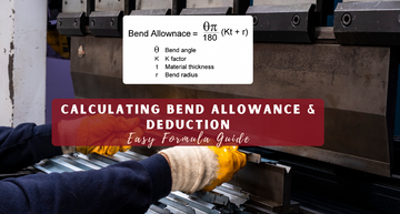
Achieving perfect sheet metal bends begins with understanding the bend allowance formula. This formula calculates the amount of material needed for a bend by determining the arc length along the neutral axis.
When you bend metal, the outer side stretches and the inner side compresses, making the neutral axis the key for flat pattern accuracy.
If your bend allowance is off, your part may end up the wrong size. In this guide, you’ll learn how thickness, bend angle, inside radius, and K-factor all fit into the bend allowance formula, plus when to use bend deduction for even better results.
Quick Insights:
- BA = (π / 180) * (R + K * T) * A
- The bend allowance formula helps calculate the developed length of sheet metal after it has been bent.
- Accurate bend allowance and deduction minimize scrap and ensure parts fit properly.
- The formula uses bend angle, inside radius, thickness, and K factor.
- Both bend allowance and deduction are vital for precise sheet metal work.
What Is the Bend Allowance Formula? Understanding the Basics
The bend allowance formula determines the amount of extra material required when bending sheet metal. When you bend metal, the material stretches on the outside of the bend. This means your flat pattern must be longer than the finished part.

The basic bend allowance formula is:
BA = (π / 180) * (R + K * T) * A
Here's what each part means:
- BA: is the Bend Allowance
- π: (Pi) is approximately 3.14159
- R: is the inside bend radius
- K: is the K-factor (a material-dependent value)
- T: is the material thickness
- A: is the bend angle in degrees.
The K factor is key to accurate bend allowance calculation. Different materials have different K factors. Steel typically uses 0.33, while aluminum might use 0.38.
You need this formula for every sheet metal project. Without it, your parts will be the wrong size after bending. The formula tells you the exact arc length of material that gets used up in the bend.
Why the bend allowance formula matters:
- Prevents costly material waste
- Ensures parts fit together properly
- Saves time by getting measurements right the first time
- Helps you create accurate flat patterns
Getting your bend allowance calculation right means your finished parts will match your design perfectly.
Bend Allowance Formula Explained: Key Variables & How It Works
The bend allowance formula utilizes four key variables to calculate the additional material required during sheet metal bending. Understanding each variable and following proper calculation steps helps you avoid common errors that lead to inaccurate measurements.
The Standard Bend Allowance Formula

The standard bend allowance formula is:
BA = π × (R + K × T) × θ / 180
Where:
- BA = Bend Allowance (in the same units as thickness)
- R = Inside bend radius (in inches or mm)
- K = K-factor (decimal between 0.25 and 0.5)
- T = Material thickness (in inches or mm)
- θ = Bend angle (in degrees)
The K-factor represents the location of the neutral axis during bending. Most materials use K-factors between 0.33 and 0.44.
For soft materials like aluminum, use a K value of 0.33. For harder materials like steel, use K = 0.44.
Example Calculation:
- Material thickness: 0.125 inches
- Inside radius: 0.125 inches
- Bend angle: 90 degrees
- K-factor: 0.33
BA = π × (0.125 + 0.33 × 0.125) × 90 / 180 BA = π × (0.125 + 0.041) × 0.5 BA = 0.260 inches
Step-by-Step Calculation Using the Bend Allowance Formula
- Step 1: Measure the thickness of your material using calipers. Record this value in decimal form, not gauge numbers.
- Step 2: Determine the inside bend radius from your tooling specifications. This equals the punch radius for air bending.
- Step 3: Find the correct K-factor for your material type. Check material charts or run test bends to verify.
- Step 4: Measure the bend angle in degrees. Use 90 degrees for right angles, 45 degrees for corner bends.
- Step 5: Plug all values into the formula. Make sure all measurements use the same units.
- Step 6: Calculate the result. Double-check your math, especially the division by 180.
Always verify your calculation with a test bend before production runs.
Key Components Explained:
- Bend Allowance (BA): The length of the arc measured along the neutral axis, which is the part of the bend that doesn’t stretch or compress.
- Neutral Axis: The imaginary line inside the material where the length stays the same during bending. The K-factor sets its position.
- K-factor (K): This value tells you where the neutral axis sits. It’s the ratio of the distance from the inside surface of the bend to the neutral axis, divided by the material thickness. Most K-factors fall between 0.3 and 0.5.
- Bend Angle (A): The angle you want to bend the sheet metal, measured in degrees.
- Material Thickness (T): How thick your sheet metal is.
Common Mistakes When Using the Bend Allowance Formula
- Using incorrect K-factor values causes the largest errors. Many people use 0.5 for all materials, but this only works for very soft metals.
- Mixing measurement units creates calculation problems. If the thickness is in inches, the radius must also be in inches.
- Confusing inside and outside radius leads to wrong results. The formula requires the inside radius, not the outside radius.
- Forgetting to convert angles happens when using radians instead of degrees. The formula requires degrees, not radians.
- Using gauge thickness instead of actual thickness creates inaccurate bends. Always measure actual material thickness with calipers.
- Applying the wrong bend angle occurs when measuring from the wrong reference point. Measure the actual angle through which the material bends.
Bend Deduction Formula: How to Calculate & When to Use
Bend deduction calculates how much material gets "lost" during the bending process, helping you determine the correct flat pattern length. Understanding the difference between bend deduction and bend allowance is crucial for accurate sheet metal fabrication calculations.
Bend Deduction vs. Bend Allowance: What's the Difference?
Bend allowance measures the arc length along the neutral axis of a bent part. It tells you how much extra material you need for the bend itself.
Bend deduction works differently. It calculates the amount you subtract from the sum of all leg lengths to get your flat pattern length.
Here's the key difference:
- Bend Allowance: Arc length of the bend (what you add)
- Bend Deduction: Material "consumed" by the bend (what you subtract)
The relationship between them is: Bend Deduction = (Leg 1 + Leg 2) - Bend Allowance
When you bend metal, the outer surface stretches and the inner surface compresses. The bend deduction accounts for this material displacement.
Most fabricators prefer bend deduction because it's easier to work with. You simply subtract the bend deduction from your total leg lengths instead of calculating complex arc measurements.
Bend Deduction Formula and Calculation Steps
The bend deduction formula is:
BD = 2 × (Bend Radius + Material Thickness) × tan(Bend Angle ÷ 2) - Bend Allowance
You can also use this simplified approach:
BD = Outside Setback + Inside Setback - Bend Allowance
- Step 1: Calculate the outside setback Outside Setback = tan(Bend Angle ÷ 2) × (Bend Radius + Material Thickness)
-
Step 2: Calculate the inside setback
Inside Setback = tan(Bend Angle ÷ 2) × Bend Radius - Step 3: Calculate bend allowance BA = (π ÷ 180) × Bend Radius × Bend Angle × K-Factor
- Step 4: Apply the bend deduction formula BD = Outside Setback + Inside Setback - Bend Allowance
The K-Factor typically ranges from 0.3 to 0.5 for most materials. Use 0.33 for soft materials and 0.5 for harder materials.
Real-World Examples Using the Bend Deduction Formula
Example 1: 90-degree bend in 0.125" aluminum
Material: 0.125" thick aluminum Bend radius: 0.125" Bend angle: 90 degrees K-Factor: 0.33
Outside Setback = tan(45°) × (0.125 + 0.125) = 0.250" Inside Setback = tan(45°) × 0.125 = 0.125" Bend Allowance = (π ÷ 180) × 0.125 × 90 × 0.33 = 0.065"
Bend Deduction = 0.250 + 0.125 - 0.065 = 0.310"
Example 2: 120-degree bend in 0.063" steel
Material: 0.063" thick steel Bend radius: 0.063" Bend angle: 120 degrees K-Factor: 0.4
Outside Setback = tan(60°) × (0.063 + 0.063) = 0.218" Inside Setback = tan(60°) × 0.063 = 0.109" Bend Allowance = (π ÷ 180) × 0.063 × 120 × 0.4 = 0.053"
Bend Deduction = 0.218 + 0.109 - 0.053 = 0.274"
Use these calculations when programming CNC equipment or creating flat patterns for laser cutting.
Also Read: Carbon Steel vs Stainless Steel: Differences, Pros, Cons & Uses
Using the Bend Allowance Formula for Accurate Flat Patterns
Determining the correct flat pattern size requires accurate use of bend allowance calculations. Charts, calculators, and proper setup techniques help you avoid costly mistakes when cutting material before bending.
How to Read and Use Bend Allowance Charts
Bend allowance charts show pre-calculated values for common material types and thicknesses. You find your material thickness in the left column and the bend radius across the top row.
Most charts use the K-factor method. The K-factor represents the position of the neutral axis within the material during bending. Steel typically uses 0.33, while aluminum uses 0.38.
Reading Chart Values:
- Material thickness (T) appears in decimal inches or millimeters
- Inside bend radius (R) shows as multiples of thickness
- Bend angles range from 30 to 180 degrees
- Values give you the bend allowance in linear units
Charts are most effective for standard materials and tooling. Custom applications need the actual formula: BA = (π × A × (R + K × T)) / 180.
Always verify the chart matches your specific material grade. Different alloys can have different K-factors even within the same material family.
Free Online Calculators & Sheet Metal Apps
Online bend allowance calculators speed up your work and reduce math errors. You input thickness, radius, angle, and K-factor to get instant results.
Popular Calculator Features:
- Metric and imperial unit conversion
- Multiple bend calculations for complex parts
- K-factor databases for common materials
- Flat pattern length totals
- Bend deduction values
Yang Tool and similar sites offer free calculators that are compatible with both phones and computers. These tools handle the math while you focus on part design.
Mobile apps enable you to calculate bend allowance directly at the machine. Many include material databases and save your common setups for quick access.
Double-check calculator results with hand calculations for critical parts. Input errors can lead to costly mistakes in production runs.
Tips for Reducing Errors in Sheet Metal Bending
Accurate measurements prevent scrapped parts and wasted material. Small errors in bend allowance calculations compound across multiple bends.
Setup Best Practices:
- Measure actual material thickness with calipers
- Use consistent tooling and setup procedures
- Test bend radius with sample parts
- Verify K-factor with material certificates
- Check springback compensation needs
Mark your flat patterns clearly before cutting. Include bend lines and directional arrows to avoid setup confusion.
Make test parts from scrap material first. This confirms your calculations work with your specific tools and setup.
Keep detailed records of successful setups. Note material lot numbers, tool combinations, and any adjustments made during production.
Calibrate measuring tools regularly. Even small measurement errors can significantly impact final part dimensions when multiplied across multiple bends.
Also Read: Hot Rolled vs. Cold Rolled Steel: What’s the Difference
Factors That Affect Bend Allowance Formula Accuracy
Several key factors can affect the accuracy of your bend allowance calculations. Material properties, geometric variables, and manufacturing methods all play important roles in getting precise results.
Material Type & Thickness
Your material choice affects the K-factor value used in bend allowance formulas. Different metals behave differently when bent.
- Material thickness changes how the metal flows during bending. Thicker materials create larger bend radii and different stress patterns. This shifts the neutral axis location.
- Ductility determines how well your material bends without cracking. High-ductility materials like aluminum allow tighter bends. Low-ductility materials like some stainless steels require larger bend radii.
- Yield strength affects springback after bending. Stronger materials spring back more, changing your final bend angle. This makes your calculated bend allowance less accurate.
Material grain direction also matters. Bending parallel to the grain gives different results than bending across the grain. The K-factor changes based on grain orientation.
Bend Radius and Bend Angle
Inside bend radius directly affects your bend allowance calculation. Smaller radii create shorter arc lengths through the neutral axis. Larger radii increase the bend allowance.
Most formulas use the inside radius plus a portion of material thickness. If your actual bend radius differs from your calculation, your bend allowance will be wrong.
Bend angle accuracy is critical for precise results. A 90-degree bend uses different calculations than an 85-degree bend. Small angle errors create noticeable length differences.
Sharp bends under 90 degrees often have different K-factors than obtuse bends. Your material may behave differently at various angles.
The relationship between radius and thickness (R/T ratio) affects material flow. Very tight bends may cause the neutral axis to shift, changing your K-factor.
Tooling & Manufacturing Processes
Die and punch geometry affects how your material flows during bending. V-die width changes the bend radius and material stress patterns.
- Air bending creates different results than bottom bending
- Press brake tonnage affects material flow and springback
- Tool wear changes bend consistency over time
- Machine deflection can alter bend angles
Bending method impacts accuracy. Air bending allows material thickness variations to affect the final radius. Coining gives more consistent results but requires higher tonnage.
Setting up variations between operators or machines creates differences. Consistent back gauge positioning and material alignment are essential for repeatable results.
Temperature during bending can change material properties. Cold working hardens some metals and affects their bending behavior.
Advanced Tips for Accurate Bending
Getting precise bends requires selecting the correct K-factor for your specific material and avoiding common calculation errors that lead to parts that don't fit properly.
Choosing the Right K-Factor
Experimental values give you better results than standard K-factor tables. Test your actual material with sample bends to find the real K-factor.
Standard tables assume average conditions. Your material might behave differently based on grain direction, age, or supplier variations.
Material hardness directly affects your K-factor value. Harder materials have lower K-factors because they stretch less during bending.
- Soft aluminum: K-factor around 0.33-0.40
- Hard steel: K-factor around 0.25-0.30
- Stainless steel: K-factor around 0.30-0.35
Run bend tests on scraps before starting production. Measure the actual bend results and adjust your K-factor accordingly.
Keep records of K-factors that work for each material thickness and type you use regularly.
Also Read: What Is Mild Steel? Complete Guide to Properties & Uses
Avoiding Common Mistakes
- Wrong bend radius causes the biggest calculation errors. Using a radius that's too small for your material thickness creates unpredictable results.
- Follow the minimum bend radius rules for your material. Most materials need at least 1x thickness for the inside radius.
- Material springback causes parts to return slightly to their original shape after bending. This affects your final angle and bend allowance.
- Account for springback by overbending slightly or adding compensation to your calculations. Different materials spring back different amounts.
- Formula misapplication happens when you use bend allowance instead of bend deduction or mix up inside versus outside dimensions.
Double-check which measurement your drawings specify. Verify your math with test pieces before cutting expensive material.
Check Out Related Products:
|
|
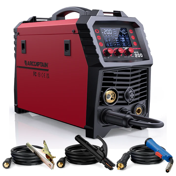
Arccaptain MIG200 Multi Process MIG WelderThe MIG200 is ARCCAPTAIN's best-selling multi-process All in 1 MIG Welder. Whether you're a beginner or a professional welder, this machine meets all your welding project needs. |
|
|
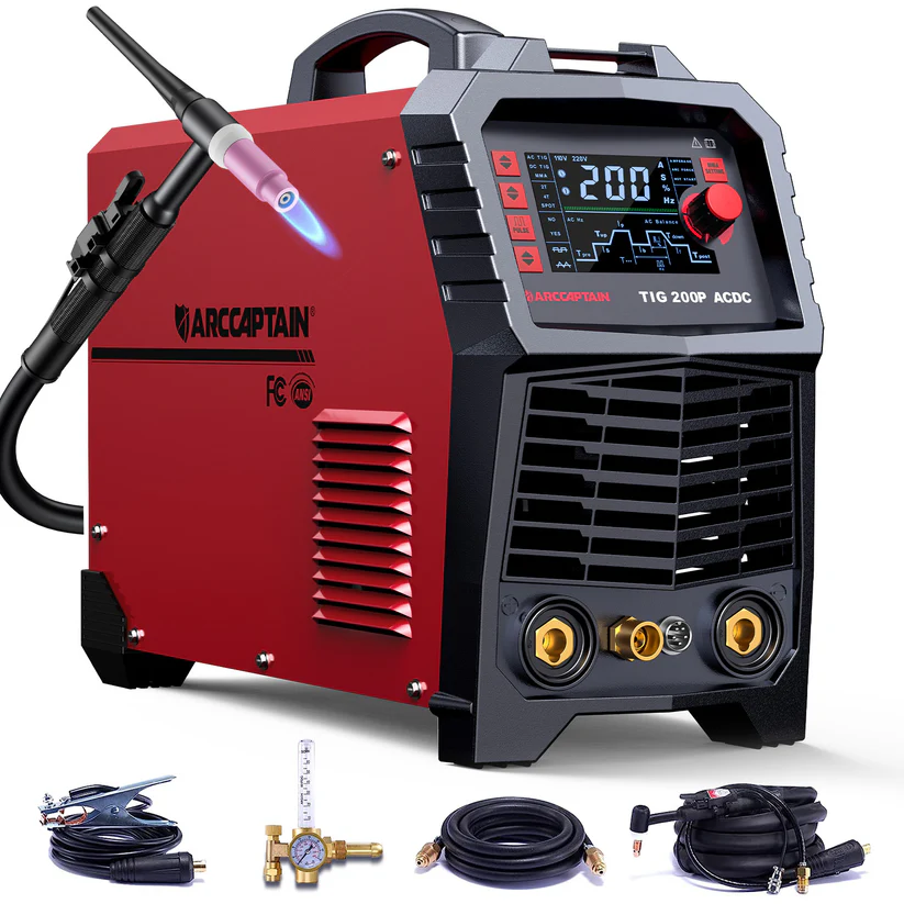
Arccaptain TIG200P AC DC Multi Process Pulse TIG Aluminum WelderThe AC DC TIG200P is our most powerful, best-selling, and top-rated high-performance Pulse Aluminum TIG Welder, highly recognized for its exceptional performance in aluminum welding and thin plate welding projects. |
|
|
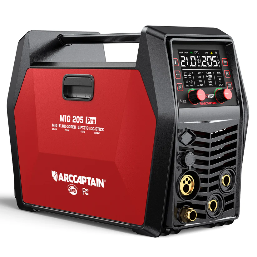
Arccaptain MIG205 Pro Multi Process MIG WelderThe MIG205 Pro features enhanced welding capabilities, localized screen language options, and improved heat dissipation for a smoother, more efficient welding experience. |
Frequently Asked Questions
These common questions cover specific calculations for 90-degree bends, the role of K-factor in determining neutral axis position, and material differences between aluminum and steel. They also address pipe bending formulas and troubleshooting when bent parts don't match design specifications.
How is the bend allowance calculated for a 90-degree bend?
For a 90-degree bend, you use the standard bend allowance formula with the angle set to 90 degrees. The calculation is: BA = 90 × (π/180) × (Radius + K-factor × Thickness).
This simplifies to: BA = 1.5708 × (Radius + K-factor × Thickness). The result gives you the arc length along the neutral axis for your 90-degree bend.
What is the k-factor bend allowance?
The K-factor represents where the neutral axis sits within your material thickness during bending. It's a ratio between the neutral axis position and the total material thickness.
Most materials have K-factors between 0.3 and 0.5. Steel typically uses 0.44, while aluminum often uses 0.42.
The K-factor directly affects your bend allowance calculation. A higher K-factor means the neutral axis sits further from the inside surface of your bend.
What is the formula for pipe bends?
Pipe bending uses a modified version of the sheet metal formula. For pipes, you calculate: BA = Angle × (π/180) × (Centerline Radius).
The centerline radius is the distance from the bend center to the middle of your pipe wall. This differs from sheet metal because pipes bend around their centerline rather than having an inside radius.
You typically do not use a K-factor for pipe bending, as the neutral axis runs through the center of the pipe.
Can I use the same formula for aluminum and steel?
Yes, you use the same bend allowance formula for both materials. The difference lies in the K-factor values you input into the formula.
Steel typically uses a K-factor of 0.44. Aluminum commonly uses 0.42. These different K-factors account for how each material behaves during bending.
The material's tensile strength and grain structure affect where the neutral axis forms. Always verify your K-factor through test bends for critical applications.
Why does my bent part not match the CAD model?
Your K-factor might be incorrect for your specific material and tooling combination. Different press brakes, dies, and material batches can change how your material bends.
Spring-back also affects final dimensions. Some materials return slightly toward their original shape after bending.
Tool wear, material thickness variations, and bending speed can impact results. Run test pieces and adjust your K-factor based on actual measurements rather than theoretical values.