Introduction
Selecting the right size for the MIG welding torch contact tip is a critical point in MIG welding gun that may affect quality of welds in addition to the duration of use before failure. In this blog, we will discuss the general rules of selecting the right MIG torch contact tip and what will happen if we mis selected the right size.
Check more of ArcCaptain MIG welders collection: MIG welder 110V, best beginner MIG welder and aluminum welders.
What is the main function of MIG torch contact tip?
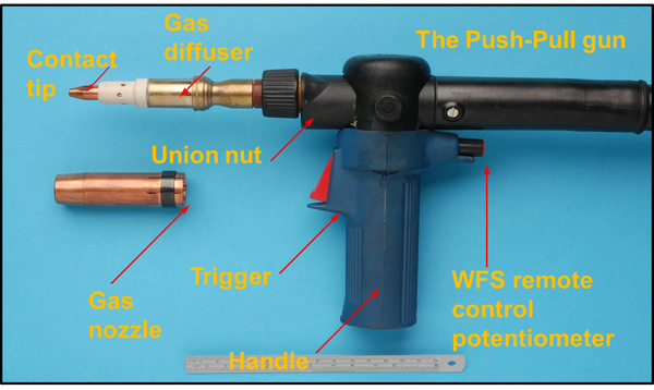
As shown in Fig.1, all the components of MIG torch are identified including the contact tip which end the walk way of wire before going to the arc and fusion zone, so, the main function of contact tip is to guide the welding wire and to transfer the welding current to the wire as it passes through the tip bore.
What is the right choice when selecting the tip size?
As a rule, you have to select the contact tip size in which the inner diameter matches the wire size but, in some cases, we can use oversized contact tips which will be explained later in this blog.
For Example: If we are going to weld by using wire with diameter size Ø 3/64 “, the recommended contact tip size is that with internal diameter 3/64 ±0.002”. The tolerances come from the applicable wire standard and the mentioned one is as per AWS A5.02 that mention the standard sizes and tolerances of solid and tubular bare wires. But there are many factors that judge the selection process.
What are the main factors that impact the selection of the right contact tip size?
There are some characteristics of the welding wire that may affect on the selection of the proper contact tip size and among these characteristics:
- Wire type and sizing tolerances.
- Wire cast
- Wire quality
Wire Type and Sizing Tolerances
MIG welding can be done whether by using MIG solid wire or flux cored wires “tubular wires” in which each type is produced with difference sizing tolerances, so you have to keep in mind before selecting the contact tip size: what is the type and size of welding wire that will be used in welding? And consequently, you will be able to determine the sizing tolerances that will be impacted on the contact tip size range.
As per AWS A5.02, the standard sizes and tolerances for solid and tubular wires are shown below:
|
Nominal Wire Size |
MIG Solid wire tolerances |
Nominal Wire Size |
MIG Flux cored wire Tolerances |
|
in |
in |
in |
in |
|
0.02 - 0.045 |
±0.001 |
0.020 - 0.025 |
………. |
|
3/64 - 3/32 |
±0.002 |
0.03 - 1/16 |
±0.002 |
|
7/64 - 1/8 |
±0.003 |
0.068 - 1/8 |
±0.003 |
|
5/32 - 5/16 |
……….. |
5/32 - 5/16 |
±0.004 |
Wire cast and helix
Wire cast refers to the diameter of the wire loop when the wire dispensed from the package and placed on a flat surface and as a rule of thumb, the wire cast should be in the range 40-45 in and if the wire cast is lower than this range, you should not use undersized contact tip.
Wire helix refers to how much the wire rises up when placed on a flat surface and it should not be greater than 1 inch as a rule of thumb. AWS A5.02 mentioned the standard packaging spools dimensions which range from 350mm and lower, that is why, the selected contact tip should be of standard size or oversized.
Wire quality
Wire quality refers to what extent the wire outside diameter is consistent where the high-quality wire has a consistent OD, so the wire passes smoothly through the contact tip without resistance due to abrasion or erosion of the contact tip and in this case, you can use the standard contact tip with ID that match the wire size and also, you can use under sized contact tip. In the case of poor wire quality, the buckling of wire is of high concern due to the inconsistent OD that is why in this case, it is recommended to use standard or oversized contact tip.
Welding process effect in selecting the contact tip size
As we know, MIG welding process can be used whether in robotic welding or semi-automatic and manual welding. In selecting the proper tip size, the process should be taken in to consideration where in case of robotic and automatic welding, the contact tip should be of ID that is slightly smaller than that of the wire size to ensure precise contact between the contact tip and wire to prevent drastic arcing and consequently increasing the life time of contact tip which is suitable for the nature of robotic and automatic welding in which noticing the contact tip is not a consistent process like in manual and semi-automatic welding.
In case of using manual and semi-automatic welding, it is recommended to use standard or oversized contact tip due to the nature of the welding gun which contain curvature to ease to be hold by the welder to get full access to the weld during welding and this curvature increases the wire cast. Also, the failure of contact tip is continuously under observation of the welder not like in the case of robotic welding.
What is the contact tip recess?
Contact tip recess is the measurement of the position of the contact tip inside the nozzle where the greater the contact tip recesses, the longer the wire sticks out of the tip as shown in fig. 2.
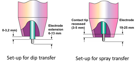
Fig. 2 Contact tip recess
Adjustable Recess Vs. Fixed Recess
As common, the contact tips are supplied with fixed recess but also can be supplied with adjustable recess to be more flexible use to adjust as required by MIG transfer mode that is why in selecting the contact tip, you should take into consideration whether the contact tip is with fixed recess or variable recess.
What will happen in case of using incorrect contact tip size?
The incorrect selection of contact tip size can cause erratic arc and poor arc performance. Using undersized contact tip will lead to the snag of wire inside the bore of contact tip which consequently leads to the burn back of wire casing deterioration of contact tip with the molten wire in addition to the difficulty of wire feed which will harm the driving wire feed rolls of the feeder.
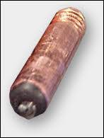
Fig. 3 Wire Burn back and deterioration of contact tip
In the case of using oversized contact tip in which the inner diameter of the tip is larger than the wire size, the wire will wander loosely as it passes through the tip. This wandering will lead to poor arc stability, heavy spatter, lack of fusion in addition to misalignment of wire to the weld. Also, in case of using oversized tip, the tip will be liable to erosion by the wire more than the case of undersized tips.
The standard MIG contact tip sizing is determined by the wire diameter of the MIG welding wire being used. Here are some general guidelines:
- For 0.023 inch diameter wire, use a 0.023 inch diameter contact tip.
- For 0.030 inch diameter wire, use a 0.030 inch diameter contact tip.
- For 0.035 inch diameter wire, use a 0.035 inch diameter contact tip.
- For 0.045 inch diameter wire, use a 0.045 inch diameter contact tip.
It is important to note that these are only general guidelines and the specific contact tip size may vary depending on the specific welding project and conditions. It is always best to consult with a welding expert or refer to the manufacturer's recommendations for the specific MIG welding wire and contact tip being used.
Read more related articles: What is Welding Slag, What is Flux in Welding.
Standard MIG Contact Tip Sizing Chart
| Wire Size | Recommended Contact Tip Size (Standard Duty) | Recommended Usage |
| 0.023”(0.6 mm) | 0.023”(0.6 mm) | tight fit joint (less space between gap), delicate materials such as stamp steel |
| 0.030”(0.8 mm) | 0.030”(0.8 mm) | Railing, cap rails, small angle iron pieces |
| 0.035”(0.9 mm) | 0.035”(0.9 mm) | Most common size for fabrication shops |
| 0.045”(1.2 mm) | 0.045”(1.2 mm) | Galvanized sheet metal |
| 0.052”(1.3 mm) | 0.052”(1.3 mm) | Plate steels with moderate amounts of rust or mill scale |


